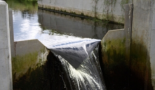
Thin-Plate Weirs, when properly installed and maintained, are one of the most accurate means of measuring open channel flows. Under field conditions, though, without proper sizing or regular maintenance a thin-plate weir will become increasingly less accurate over time.
Weir Pools – Sizing
In order for a weir to properly measure flow, a body of water must be formed upstream of the weir. This water, know as a weir pool or weir pond, must poses sufficient bottom and side contractions and extend far enough upstream so as to condition the flow as it approaches the weir.
The suggested size of weir pools surprises many potential weir users. Frequently, applications where weirs were under consideration change to flumes or primary devices when the size of the weir pool is determined.
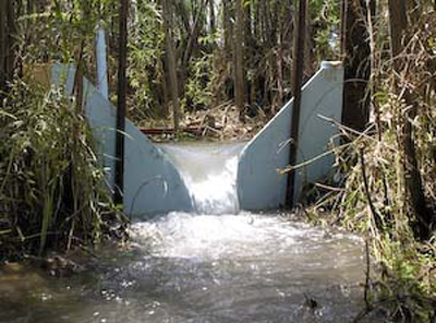
The walls of a weir should extend at least 2 times the maximum anticipated head, Hmax, on either side of the weir crest, which should in turn be at least 2 times the maximum anticipated head above the floor of the channel. Additionally, for irrigation applications in natural channels, the rectangular channel is recommended to extend 15 to 20 feet [4.57 to 6.10 m) upstream.
The goal of the weir pool is to normalized the velocity profile and reduce the velocity of approach to no more than 0.3 to 0.5 ft/s [0.0914 to 0.1524 m/s].
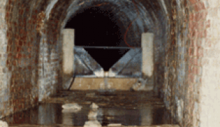
Weir Pools - Maintenance
A weir pool acts to still water as it approaches a weir plate. In stilling the water, the velocity is reduced, inducing sedimentation of suspended sediments and silt. Over time, the sediments build up to the point where the bottom contraction of the weir pool is too shallow for the weir to operate accurately. When this occurs, the sediments must be removed from the weir pool – either through dredging or sluicing through the weir plate (if the plate has a cleanout in it).
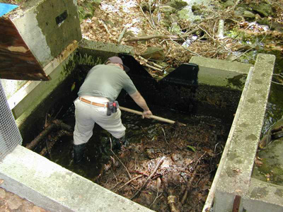
Failure to remove the sediments and debris in a weir pool will result in the effective floor of the pool to rise, which in turn increases the velocity of water though the channel – resulting in an installation that will under-read the actual flow rate as the flow never fully develops and instead shoots over the weir crest.
Weir Crest – Maintenance
Research has shown that to achieve maximum accuracy the weir crest of a thin-plate weir must be regularly maintained. A thin-plate weir crest must be regularly checked for rounding as well as nicks and abrasions, while the weir itself must be checked for surface smoothness near the weir crest.
It is for this reason that many weirs (or at least their crests) are fabricated from stainless steel or fiberglass – both of which can either hold an edge or be field dressed to hold an edge. Wood, aluminum, and plastics do not possess sufficient surface smoothness, abrasion resistance, or are able to be fabricated sufficiently thin enough [1/8-inch [0.3175 cm]).
In maintain a weir crest, the edges of the crest must be kept perpendicular to each other. Rounding of the upstream edge of the crest will result in flow inaccuracies as will damage. Where nicks or abrasions of the weir crest edge have occurred, any material extending out from the face of the weir or up from the crest should be filed back so that it is edge or surface is flush again. It is important not to file into the weir in the attempt to remove damage.
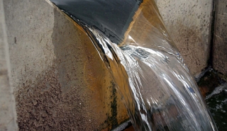
Free-Spilling Discharge
Weirs are designed to operate under free-spilling / free-flow conditions. They are not designed for submergence. For this reason in addition to setting a weir crest a given height above the channel flow, consideration must also be given to setting the weir crest so that it is a minimum of 2 to 6 inches [5.08 to 15.24 cm] above the maximum downstream water surface.
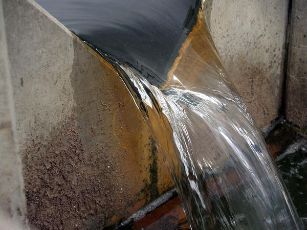
A sufficiently high downstream water level may not allow the water flowing over the crest of the weir (the nappe) to be sufficiently aerated. Also, if the surface of the water downstream of the weir rises above the crest of the flume the flow is submerged, meaning that the actual discharge is less than the indicated discharge. While submergence can be corrected for, the difficult in measuring the flow and the cost of the additional instrumentation are great deterrents to it.
Point of Measurement and Gauge Zero
Unlike a flume where the point of measurement is usually in the structure and measured from the floor, the point of measurement for a weir is both upstream of the weir itself and the gauge zero is above the weir pool floor.
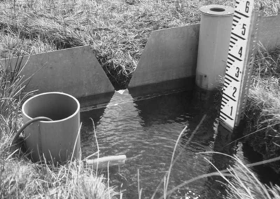
The point of measurement in a weir is upstream of the weir itself a distance of 3 to 5 times Hmax. At this point the head in the weir pool is essentially unaffected by the drawdown of the water’s surface at it approaches the weir crest.
As discussed above, to develop a proper weir pool, the crest of a weir must be set a minimum of 2 times Hmax above the channel floor. This elevation is the gauge zero, from which the flow level in a weir installation is measured (at the point of measurement upstream of the weir itself). Under flow conditions, if the gauge zero is not know it can be difficult to transfer measurements of how high the weir crest is above the channel floor back to the point of measurement. As such, verification of a weir gauge zero is best performed when there is no (or little) flow.
Minimum Flow Rates
While weirs a frequently viewed as being devices that are best able to accurately measure low flows, the truth is somewhat different. Of the various standard weir configurations, the 22-1/2º V-notch has the lowest minimum flow rate (3.990 gpm [0.2518 l/s]). This flow rate, though, is actually quite high when compared to several smaller sizes of flumes. Both the 0.4-foot HS (0.0718 gpm [0.0045 l/s]) and 1-inch Parshall / Montana (1.460 gpm [0.0921 l/s]) flumes have lower flow rates.
Maximum Head
The formulas for weir have been empirically derived and are not necessarily suitable for extrapolation. Much of the data collected for weirs has been for heads up to 2.0-feet [60.96 cm]. Although some data is available for higher heads, the general agreement is that 2.0-feet [60.96 cm] should be view as the maximum head for which good quality results can be obtained.
Images: PolarTREC, Def/Mo via Flickr, The Lancaster Environment Centre